Evil Science Audio
Custom Guitar Amp Prototype Build
This project was for a business customer interested in creating a new 55 watt guitar amplifier. The prototype here is for testing the electronic design, and for adding/trying modifications.
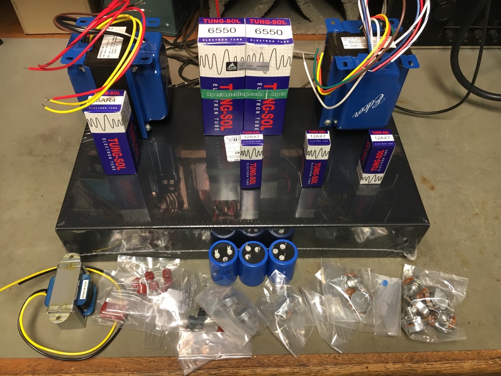
The mock layout is shown here, however it was reversed left-right so the inputs will be on the left opposite of the power supply. The goal was to make a smart layout that looked good, with plenty of room for additions or modifications.
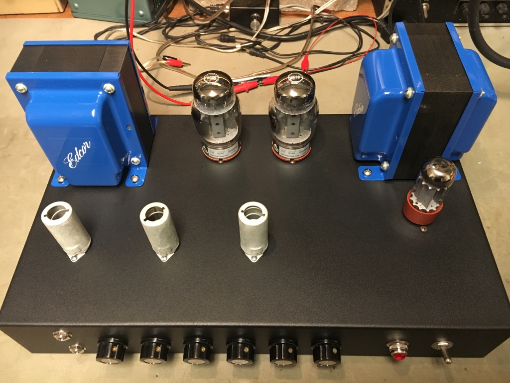
Here’s a top view of the chassis with everything mounted. Some items were placed as assembly progressed.
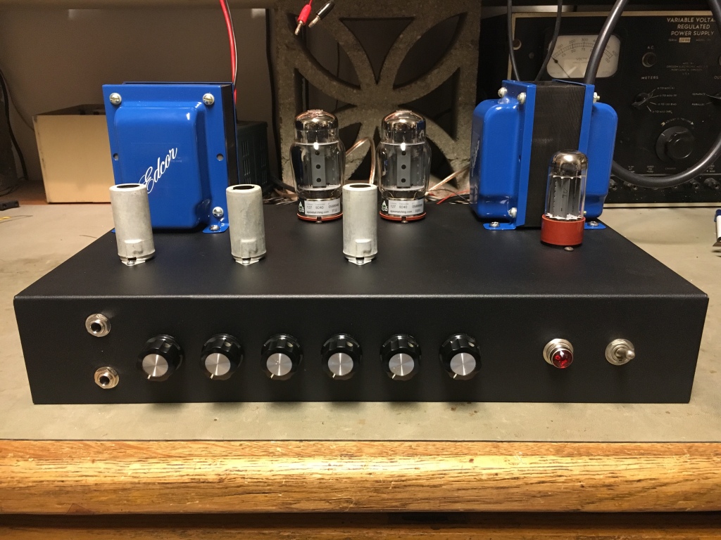
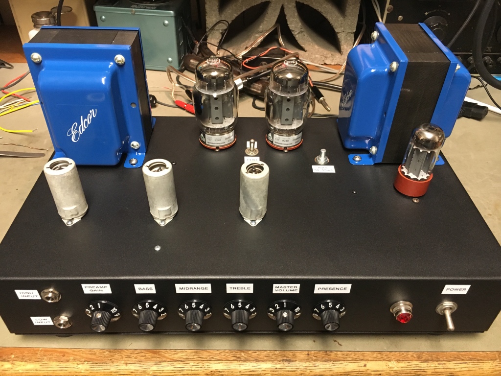
The front view of the same.
Here we can see two things, the power is on with the pilot lamp lit, and the addition of a toggle switch near the output tubes to offer connection options of standard or distributed load.
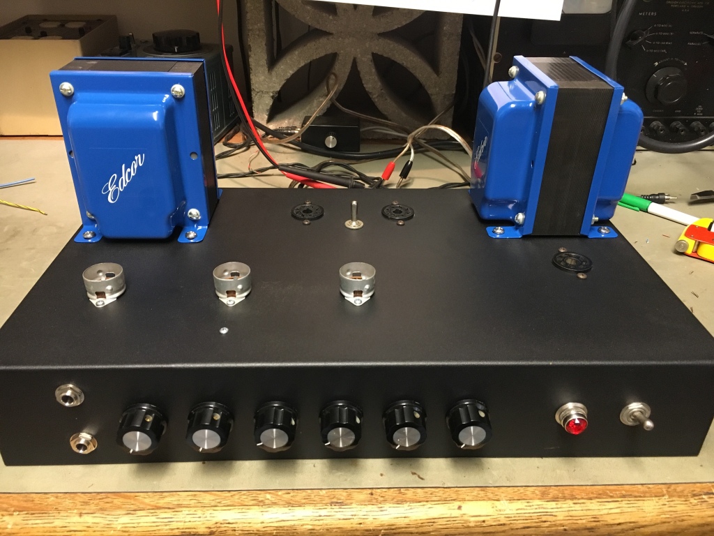
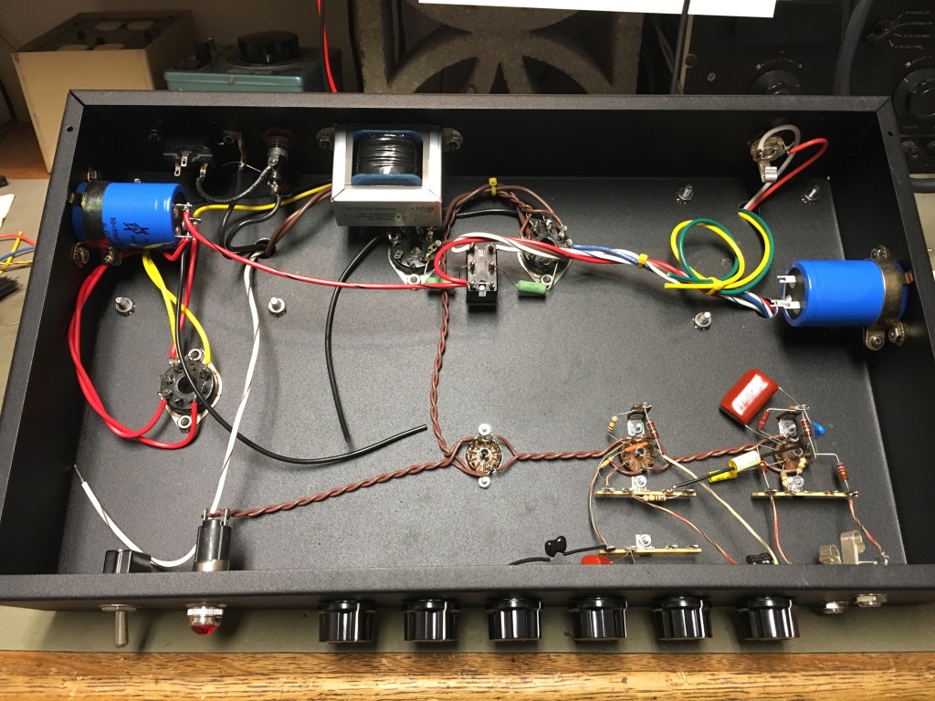
Assembly proceeding inside.
This is the final product as delivered to the customer for testing. Using 6550 output tubes at 475 plate volts via the 5AR4 rectifier yielded 55 watts pentode connected, 50 watts distributed load. The gain stages and driver tube are all 12AX7s. There was no audible noise or hum with no input connected, so the grounding is good.
More to come as the project progresses!
6KV8 Push-Pull Driver Board
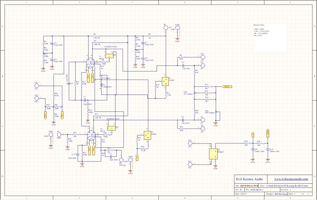
Here’s a look at a design project I’m working on. This is a driver circuit for a push-pull amplifier designed around the 6KV8 tube. The 6KV8 tube is a high-gain triode with good linearity and high transconductance coupled with a frame-grid pentode also having a high transconductance. Tubes like this were designed for television applications, not audio. Here the triode sections of the two 6KV8s are connected as an active-loaded gain stage, which then feeds the two pentode sections acting together as a phase inverter and driver section. The pentodes use IXYS programmable current sources to help linearize their operation. The circuit includes local power supply filtering and the negative bias supply. There are two options for feedback loops. One loop goes to the cathode of the lower pentode, and makes a standard feedback loop. The other is plate-to-plate loops from the output stage via connections LF1 and LF2. These are both subject to some experimentation when the prototype PCBs arrive and are stuffed.
This is the art of the PCB itself. This is where my project is different from what you’ll usually see in PCBs for vacuum tube audio. Other than the tube sockets, all components are surface mount. This is the more modern assembly method for electronics. The possible disadvantages are how the PCB will handle waste heat, and the limits on component selection. You can see in red the large copper area used as a heat sink for the current source components, which if effective will eliminate the use of a standard aluminum heat sink.
More to come when the prototype is ready to test!
The 89Y SE Headphone Amplifier
Completed!
In the traditional “Darling” style, it gets .75 watts per channel! The 6C8G is a really nice tube, unfortunately it gets overlooked.
Push-Pull 7C5 Amplifier in Vintage Style
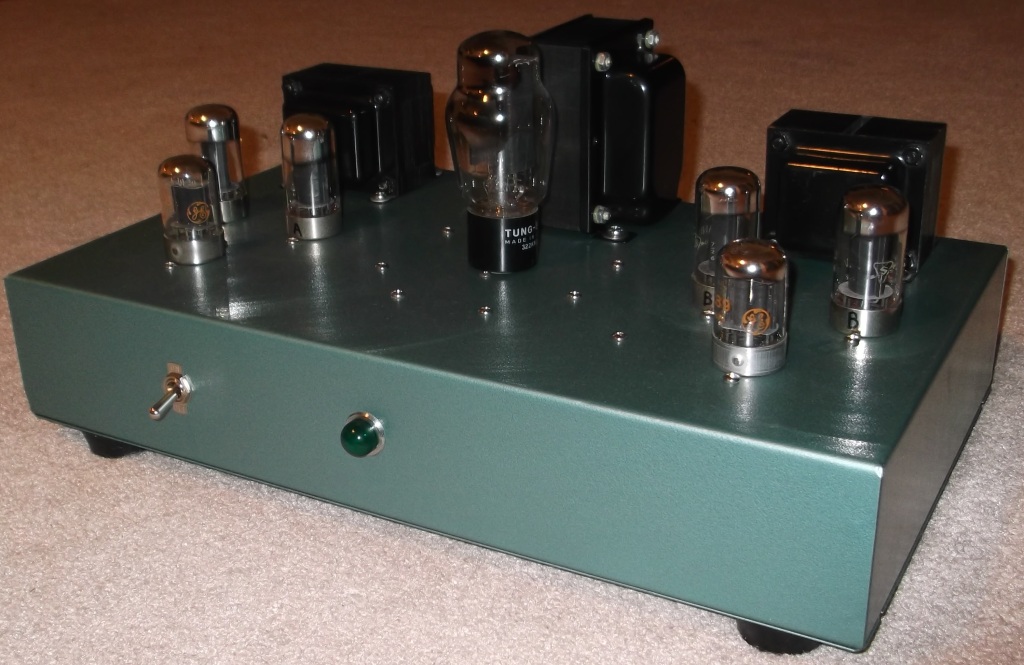
Here it is, finally! Oh, and I hope you like green! This is a complete rebuild of my very first amplifier. Using everything I’ve learned since that time, I began this project with the goal of creating an artistic and functional version of that design. The tubes, output transformers, and a few internal parts remain from the original build. A new power transformer was used, as well as the new chassis, sockets, and other internal parts. Being mostly the same circuit and parts, it sounds exactly the same.
The schematic shows what few changes were made:
- The 7C5 screen grids are supplied from the plate B+ through 100 ohm resistors instead of a separate filter section. This is more protective of the 7C5s, whereas the prior connection gave no noticeable improvement.
- The power supply filter capacitors are reduced to 50 & 50 µF, from 100 & 100 µF. 100 µF is too large a value to follow a standard 5U4 rectifier, and can cause the tube to arc-over internally.
- The 7C5 cathodes are bypassed to ground instead of to B+, which is known as “Ultrapath”. Other than more expensive higher voltage capacitors, “Ultrapath” resulted in no discernible difference.
The 89Y SE Amplifier – In Progress
My next project has been cut, painted, and mechanically assembled. This is going to be a small single-ended amplifier with speaker and headphone output similar to the 1626 “Darling” amplifier below. The 89Y output tube is a military grade “type 89 – triple-grid amplifier” with a micanol base and graphite coated glass. Type 89 is a precursor to Type 41, 6K6/G/GT, 7B5, and 6AR5. It has a cap for control-grid connection and separate screen-grid connection pin at the base. Here it will be connected as a triode and driven by the 6C8G. The 6C8G is a tube I haven’t used before which has good linear curves and looks good in the amplifier. It contains two triodes, one of which has a grid connection at the top cap. If both stages prove linear enough and the output impedance isn’t too high, no loop feedback is planned. The schematic I’ve worked up for it is still on paper and not installed underneath the chassis yet. The output transformers aren’t cheapies this time! These are Transcendar 8K:8Ω from Gerry at Transcendar Audio Transformers.
More to come!
Single-Ended 807 Amplifier
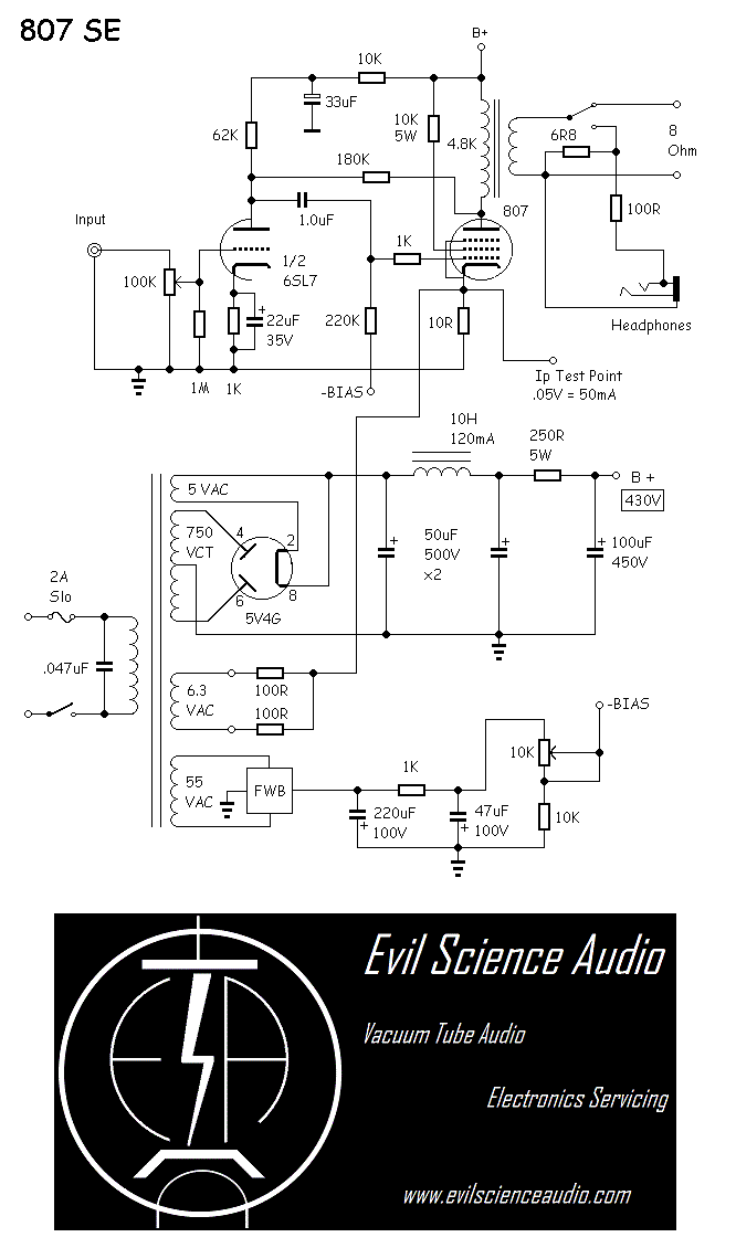
This amplifier was built on-the-cheap. I used salvaged transformers purchased well below online prices and 807 tubes which are still reasonably priced. 7 watts per channel. I won an impromptu local “shootout” with this. Recently added speaker/headphone switch and headphone jack. Now it’s personal!
How it was done: Single-ended pentode mode, with primary-side feedback, and fixed bias operation.
A look at the construction:
Comments
- 현재 접속자 4 명
- 오늘 방문자 155 명
- 어제 방문자 374 명
- 최대 방문자 2,574 명
- 전체 방문자 268,747 명
- 전체 게시물 578 개
- 전체 댓글수 0 개
- 전체 회원수 5 명

